Features and typical applications
Key Features
- Quick response - T90 ≤ 3 sec
- Extremely suppressed ranges
- High corrosion resistance
- High temperature capability up to 180°C
- Infallible containment
- Integration into Ex d housings
Typical Applications
- H2 & O2 purity – water electrolysis
- Metallurgical process gases - blast furnace
- Steel - heat treatment & hardening
- Petrochemistry - synthesis & reformer gas
- Gas purity - PSA, LEL/UEL & inert gas
- Coal, wood & biogas gasification
- Corrosive process gases with Cl2, H2S and HCl
- Processes with H2, water vapor and high dew points
- Processes in hazardous areas
Description
Description
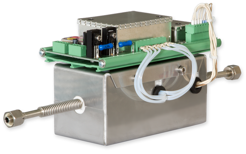
LFE's unique thermal conductivity detector is the heart of LFE's CONTHOS process TCD gas analyzer and has proven itself since 1979 in a wide range of applications. The TCD combines quick response, high corrosion-resistance and high-temperature capability without compromise. Further features are its extraordinary measurement stability, low range capabilities as well as highly suppressed ranges.
LFE's Thermal Conductivity Detector (TCD)
In conventional gas analyzers utilizing the principle of thermal conductivity a heated object is suspended in a volume containing the sample gas. Electrical energy passed through the object results in the object heating up and attaining an equilibrium temperature which is primarily dependent upon the thermal conduction properties of the surrounding gas. This temperature is normally measured directly as a change in the electrical resistance of the heated object itself.
LFE´s unique principle modifies this "classical" method by spatially and electrically decoupling the heated element from the temperature sensing element. The specially designed geometry of the TCD cell in conjunction with the decoupling effectively suppresses undesired competing thermal effects (i.e. free and forced convectional effects). The result is an instrument whose quick, stable response requires no compromise between gas flow and response time.
Features
- micro-miniaturized for quick response behavior
- corrosion and temperature resistant
- made of aluminum oxide (Al2O3), glass and SiOx-coated platinum sensor filaments


Technical data
Technical Data
Enclosure & Electrical Data
|
Technical specifications subject to change without notice |
|
|
Dimensions |
refer to dimensional diagram found in product data sheet |
|
Weight |
1.2 kg |
|
Power requirements |
24 VDC; 25 VA max. (during initial heat-up phase) |
|
Data / service interface |
RS232 or Ethernet (Telnet protocol) in conjunction with isolated logic level converter
|
Measuring characteristics
|
Technical specifications subject to change without notice |
|
 |
Note: The technical data is valid for operation of the OEM TCD within LFE's CONTHOS gas analyzer. |
|
Measuring principle |
Thermal conductivity (TCD). Difference in thermal conductivity (Δλ) of various gases |
| Measured quantity | Concentration of a particular gas component in binary and quasi-binary mixtures |
| Gas interference |
For the analyzer configuration, the knowledge of the sample gas composition is necessary. In complex (non-binary) gas mixtures, the measurement results may be affected by interfering components. Through the use of dynamic interference correction, the interference effects can be suppressed under certain circumstances. This must be implemented by the customer within his system or in conjunction with the appropriate optional interface expansion modules. Physical interference suppression is sometimes possible with certain gas combinations due to the wide temperature range of the CONTHOS' TC detector. |
|
Measuring ranges |
Measured value signal output as raw value lowest range: 0 - 0.5% H2 in N2 or 99.5-100% H2 in N2 (or equivalent Δλ) |
|
Calibration |
The device outputs RAW values that are neither fine-calibrated nor linearized. The customer must provide the appropriate algorithms. |
| Detector operating temperature |
TCD standard operating temperature: 70°C |
|
Warm-up time |
dependent upon TCD operating temperature as well as the ambient temperature: |
|
Response time t90 |
≤ 3 sec (at 60 l/h gas flow and minimum signal dampening level) |
|
Influence of gas flow |
between 3 - 30 l/h: < 0.5% of range span for a gas flow change of ±10 l/h Higher flow rates up to e.g. 120 l/h are possible. At these higher flow rates it is recommended that the analyzer be calibrated at the operating flow rate. |
| Pressure drop | approx. 0.7 mbar at 60 l/h N2 |
|
Pressure influence |
The TCD principle has a normally negligible pressure dependency. At very low ranges it can be seen as a proportional signal offset. |
|
Detection limit 1 |
≤ 0.5% of span (at signal dampening level: 1 sec) |
|
Reproducibility 1 |
≤ 0.5% of span |
|
Response drift 1 |
Zero: ≤ 1% of span per week |
|
Influence of inclination |
no influence |
|
Sample gas requirements |
|
|
Sample gas temperature |
min.: +5°C |
|
Sample gas dew point |
Dew point low enough so as to prevent condensation in the gas paths under all ambient temperature conditions |
|
Particles in sample gas |
The sample gas must be free of particles and aerosols. |
|
Sample gas pressure |
max. 300 mbar above atmospheric pressure |
|
Sample gas flow |
minimum: 3 l/h |
Materials
|
Technical specifications subject to change without notice |
|
|
Materials in contact with sample gas |
|
|
TC Detector |
Al2O3 ceramic and sapphire, glass and SiOx-coated Pt measuring filaments |
|
Gas lines |
Standard model with synthetic tubing: PTFE / PFA |
1 at constant temperature and pressure
- NOTE 1: All application and implementation details such as e.g. ranges and interfacing options must be clarified with manufacturer and evaluated for feasibility.
- NOTE 2: The technical data is valid for analyzer operation with pure bottled gases. Instrument specifications are based on binary or quasi-binary gas mixtures. Deviations from the above data can occur in conjunction with process gases depending upon the gas quality and the degree of sample handling.
- NOTE 3: The LFE OEM TCD is neither explosion-proof nor intrinsically safe in terms of explosion protection.
- NOTE 4: The LFE OEM TCD may not be employed for the analysis of ignitable gas mixtures. The customer must ensure compliance with applicable regulations when using the unit with flammable or toxic gases or when installing within hazardous areas.
- NOTE 5: The customer must ensure that the sample gas is dry and free of particulates.
Downloads
Downloads 
LFE OEM Thermal Conductivity Detector (TCD)
Technical specifications subject to change without notice

