Features and typical applications
Key Features
- Oxygen specific analysis utilizing paramagnetic sensor
- Magnetomechanical measuring principle (dumbbell principle)
- Fast response T90 ≤ 5 sec
- Temperature controlled for increased stability and performance
- Up to 3 measuring ranges
Typical Applications
- Flue gas control analyzer
- Inertization plants
- Biogas O2 measurement
- Air separation, O2 gas purity
- Power plants, metallurgical, chemistry, petrochemistry
Description
Description
The CONTHOS 3 PMD state-of-the-art process gas analyzer is an analytical instrument developed for use in process industry.
Some of the outstanding technical features of LFE's 3rd generation, microprocessor-controlled gas analyzer for oxygen analysis are:
- Temperature controlled paramagnetic sensor
- Magnetomechanical measuring principle ("dumbbell" type)
- High selectivity to O2
- Fast response time: time constant < 5 sec
- Excellent precision and outstanding performance for ranges from 0 - 5 vol.% O2 up to 0 - 100 vol.% O2
- Optional automatic pressure compensation
- Intuitive user-interface based on NAMUR recommendations
- Automatic self-diagnosis
Oxygen sensor
The basic measuring principle of the CONTHOS 3 PMD makes use of the fact that oxygen has a paramagnetic susceptibility that is significantly greater than other gases. This property causes oxygen molecules to be attracted much more strongly into an inhomogeneous magnetic field than other gases.
The paramagnetic sensor employed in the CONTHOS 3 PMD is of the so-called "dumbbell" type utilizing the magnetomechanical measuring principle. Two miniaturized, nitrogen filled gas spheres configured in a dumbbell shape are symmetrically suspended in a strong, inhomogeneous magnetic field. Any oxygen contained in the surrounding (sample) gas is drawn into the magnetic field thereby displacing the glass spheres and forcing the dumbbell to rotate outward. The resulting torque is proportional to the oxygen concentration.
A mirror mounted on the rotational axis of the dumbbell reflects a beam of light onto a pair of photocells which detect any rotational displacement. The photocells are part of a control loop which subsequently drives current through windings arranged around the dumbbell. The current through the windings generates an electromagnetic counter moment which moves the dumbbell back to its null position. The required current level is proportional to the oxygen concentration and as such is passed on to the CONTHOS' signal processing unit.

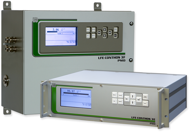
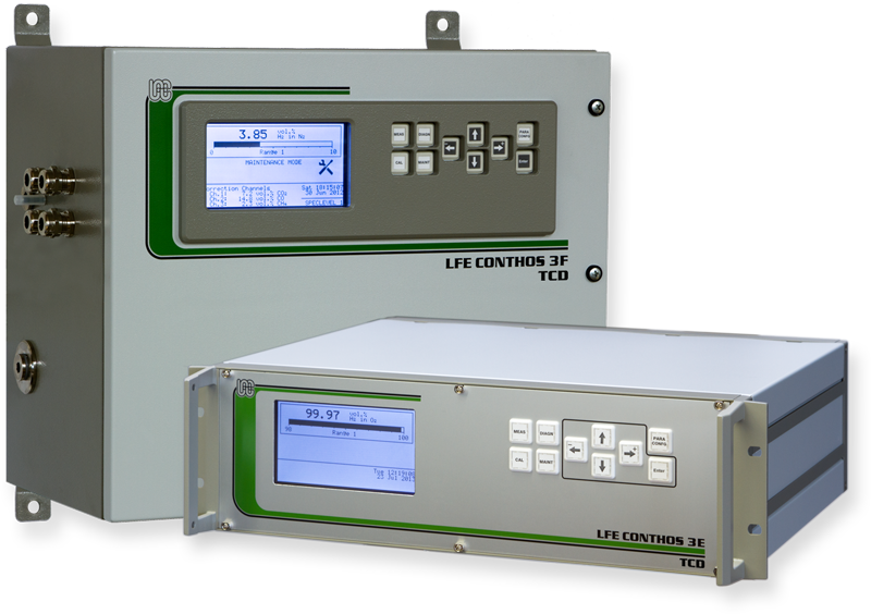
Model variations
Model variations
CONTHOS 3E-PMD
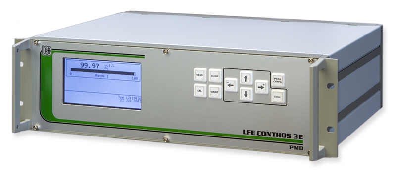
General purpose
19" rack housing
(protective class IP40)
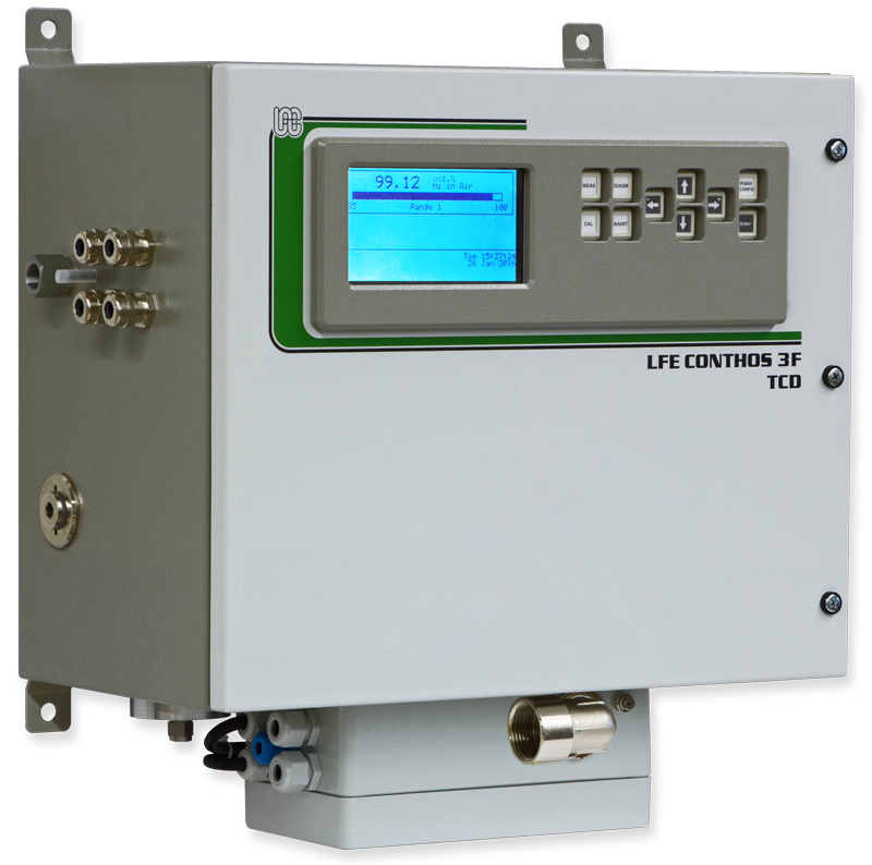
CONTHOS 3F-PMD
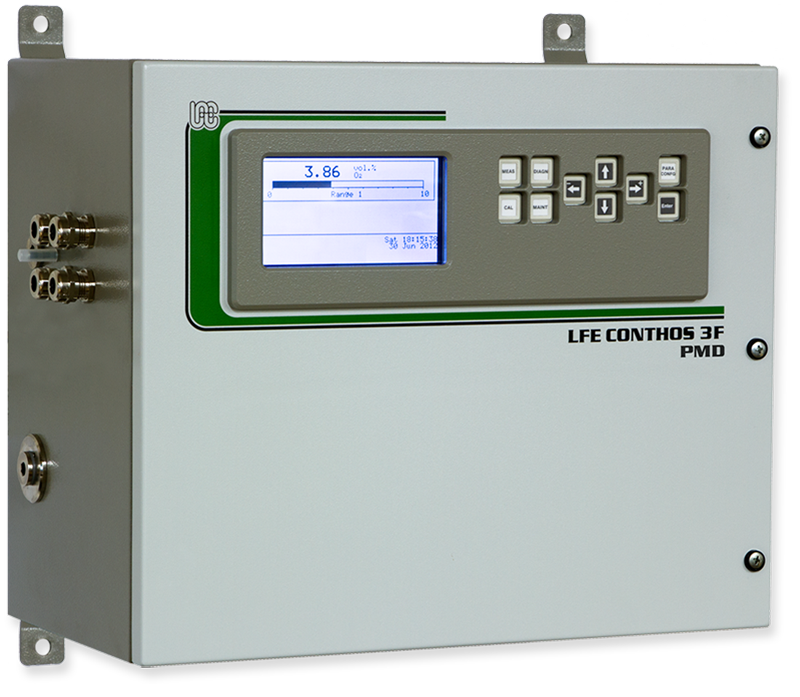
General purpose
Field housing
(protective class IP65)
Options
- Maximum 3 switchable ranges: independently configurable; suppressed ranges as special solution on request
- Automatic pressure compensation (from 800 to 1200 mbar absolute; extended pressure range on request)
- Digital I/O board for remote range switching, range identification, threshold contacts, etc.
- Interference correction in conjunction with external, selective gas analyzers for multiple gas constituents
- RS-485 interface with Modbus RTU protocol
- Modbus TCP
Technical data
Technical data
Enclosure & Electrical Data
| CONTHOS 3E PMD 19” rack housing | CONTHOS 3F PMD Field housing | |
|---|---|---|
|
Technical specifications subject to change without notice |
||
|
|
|
| Housing | 3HE/ 84TE housing for mounting in 19" cabinet |
purgeable steel housing for wall mounting; with separate compartments for the electronic components and the analytical components |
| Dimensions (H x W x D) |
3HU / 84TE 133 x 483 x 427 mm |
434 x 460 x 266 mm |
| Weight | approx. 10 kg | approx. 25 kg |
| Power requirements | 100-240 VAC (48-62Hz; nominal voltage range: 88-253 VAC; 100 VA max. during warm-up period) | |
| Sample gas connectors | Standard: Swagelok® (SS 316) for tubing o.d 6 mm Option: Swagelok® (SS 316) for tubing o.d. ¼" |
|
Measuring Characteristics
| CONTHOS 3E PMD 19” rack housing | CONTHOS 3F PMD Field housing | |
|---|---|---|
|
Technical specifications subject to change without notice |
||
| Measuring principle | Paramagnetic sensor ("dumbbell" type) | |
|
Measured quantity |
Oxygen concentration in gas mixtures |
|
|
Measuring ranges |
Up to 3 independently configurable, switchable ranges. Standard measuring range: 0-100% or 0-25% O2 (other ranges on request) Range switching is accomplished manually, automatically and/or remotely (via optional digital inputs).
|
|
| Response time T90 | < 5 sec (dependent upon gas flow and analyzer configuration; integration time configurable) | |
| Detector operating temperature | Standard operating temperature: 55°C | |
| Pressure influence | No pressure influence at 0% O2 Without optional pressure compensation: response changes proportional to pressure With pressure compensation: no influence btwn. 800 - 1200 mbar |
|
| Detection limit 1 | ≤ 1% of span | |
| Reproducibility 1 | < ± 0.03 % O2 | |
| Linearity 1 | Response intrinsically linear | |
| Zero drift 1 | < ± 0.1 % O2 / week | |
| Ambient temperature influence | Zero: < ± 0.5 % O2 per 10 K Span: < ± 2% of measured value per 10 K |
|
| Influence of inclination | Baseline offset ≤ 0.02 vol.-% O2 per 1° deviation from the horizontal | |
| Calibration | Manual: 2-point (offset/span) calibration (The optimal span gas concentrations should be chosen between 75 and 100 % of the corresponding range). Option: automatic or remote calibration in conjunction with the optional digital I/O board or Modbus interface (RS485 or TCP) |
|
| Pressure compensation | optional: from 800 to 1200 mbar absolute; extended pressure range on request | |
| Interference correction | for static and/or dynamic interference correction (dynamic correction only in conjunction with the optional analog inputs or Modbus interface (RS485 or TCP) One of the prerequisites for dynamic interference correction is the availability of a selective signal, proportional to the particular gas component to be corrected for. The processing of analyzer ranges with a suppressed zero range is not possible. |
|
Materials
| CONTHOS 3E PMD 19” rack housing | CONTHOS 3F PMD Field housing | |
|---|---|---|
|
Technical specifications subject to change without notice |
||
| Materials in contact with sample gas | ||
| Paramagnetic sensor | glass, stainless steel 1.4571, Gold, Viton, Platinum-Iridium, Epoxy, Nickel | |
| Sample gas connectors | Standard: stainless steel (SS 316; similar to 1.4401) | |
| Sample gas lines | standard: PTFE optional: stainless steel tubing (SS 321 - similar to 1.4541) and 1.4571 |
|
Instrument Interface
| CONTHOS 3E PMD 19” rack housing | CONTHOS 3F PMD Field housing | |||
|---|---|---|---|---|
|
Technical specifications subject to change without notice |
||||
| Data display, inputs & outputs | ||||
|
User interface |
LC-display (40 characters x 16 lines) + bar graph |
|||
|
Analog signal output |
2 independently configurable, galvanically isolated analog outputs (with common ground; RLoad = 600 Ohm max) |
|||
|
Digital outputs |
Instrument status (NAMUR NE 107 compliant) via floating contacts (28 V max.; 350 mA max.) |
|||
| Analog inputs (optional) |
3 galvanically isolated, configurable analog inputs for interference correction and pressure compensation 0 – 20 mA or 4 – 20 mA (Ri = 50 Ohm) |
|||
|
Digital I/O |
Digital inputs: 8 configurable, optically isolated inputs (6 - 24 VDC; 10 mA max.)
Digital outputs: 7 configurable, floating relay contacts (28 V max.; 350 mA max.)
|
|||
|
Modbus interface |
|
|||
| Service interface | non-isolated serial interface for accessing the instrument's configuration | |||
1 at constant temperature and pressure
- The stability data is valid for analyzer operation with pure bottled gases. Instrument accuracy is based on binary or quasi-binary gas mixtures. Deviations from the above data can occur in conjunction with process gases depending upon the gas quality and the degree of gas handling.
- Unless otherwise specified the CONTHOS gas analyzer is neither ex-proof nor intrinsically safe in terms of explosion protection.
- The CONTHOS may not be employed for the analysis of ignitable gas-mixtures. The customer must ensure compliance with applicable regulations when using the analyzer with inflammable or toxic gases or when installing within explosion endangered environments.
- The customer must ensure that the sample gas is dry and free of particulates.
Downloads
Downloads 
CONTHOS 3-PMD | Paramagnetic Oxygen Gas Analyzer
CONTHOS 3
Sample Applications
Iron and Steel production – blast furnace - Process Gas Analyzer
Heat Treatment and Hardening Process - Hydrogen Process Gas Analyzer
Water Electrolysis Process - Hydrogen Process Gas Analyzer
Hydrogen Cooled Generators - TCD Process Gas Analyzer
Coal Gasification Gas Processing - Process Gas Analyzer
Air Separation Plant and Bottling - Process Gas Analyzer
Synthesis Gas - Syngas Processing - Hydrogen Process Gas Analyzer
High Temperature Applications - Hydrogen Process Gas Analyzer
Refinery Continuous Catalyst Regeneration - TCD Process Gas Analyzer
Technical specifications subject to change without notice

