Features and typical applications
Key Features
- Extremely long term stable analysis of H2 and noble gases in binary and quasi-binary gas mixtures with lowest ranges up to 0 – 5000ppm
- Extremely suppressed ranges up to 99.5 - 100%
- Ultra-fast response T90 ≤ 3 sec
- Highly corrosion resistant TCD cell with Al2O3, glass and quartz for process gases with Cl2, HCl, SO2, H2O
- Cross compensation of up to 3 components for reduction of intereference
Typical Applications
- H2 and O2 purity in electrolysis of water
- Metallurgical process gases such as blast furnace, converter steel or direct reduction
- Steel industry: Heat treatment & hardening
- Petrochemistry: Gas processing to synthesis gas, reformer gas & coal gasification
- Monitoring of gas purity, pressure swing adsorption, gas turbine cooling gas, LEL/UEL as well as inert gases
Description
Description
The CONTHOS 3 state-of-the-art thermal conductivity gas analyzer is an analytical instrument developed for on-line monitoring in process industry applications.
The special outstanding technical features of LFE's microprocessor controlled gas analyzer are:
- Thermal conductivity detector - thermostat controlled temperature from 50°C to max. 180°C
- High corrosion resistance in the entire sample gas path
- Low detection limit in the lower ppm range
- Response highly independent of the gas flow
- Extraordinarly high long-term stability
- Intuitive user-interface based on NAMUR recommendations
- Automatic self-diagnosis
- Optional dynamic interference correction of up to 3 gases in conjunction with external, selective gas analyzer channels
The technical features of the unique CONTHOS 3 gas analyzer open up new areas of application for the thermal conductivity principle, as well as help to eliminate weak points in present analysis problem solving.
The selected thermostat temperature of the detector can help minimize the cross interference of possible accompanying gas components. Furthermore, accompanying gases can be measured by means of suitable external measuring methods and an interference correction of these components can be carried out.
First developed in 1979 the LFE CONTHOS gas analyzer has proven itself in many years of continuous operation in fields such as:
- in corrosive process gases in the chemical and petrochemical industry
- in metallurgical applications such as process gas and hardening & heat treatment
- in all of the "classical" applications of the TCD principle with outstanding measurement performance
LFE's Thermal Conductivity Detector (TCD)
In conventional gas analyzers utilizing the principle of thermal conductivity a heated object is suspended in a volume containing the sample gas. Electrical energy passed through the object results in the object heating up and attaining an equilibrium temperature which is primarily dependent upon the thermal conduction properties of the surrounding gas. This temperature is normally measured directly as a change in the electrical resistance of the heated object itself.
LFE´s unique principle modifies this "classical" method by spatially and electrically decoupling the heated element from the temperature sensing element. The specially designed geometry of the TCD cell in conjunction with the decoupling effectively suppresses undesired competing thermal effects (i.e. free and forced convectional effects). The result is an instrument whose quick, stable response requires no compromise between gas flow and response time.
Features
- micro-miniaturized for quick response behavior
- corrosion and temperature resistant
- made of aluminum oxide (Al2O3), glass and SiOx-coated platinum sensor filaments


Model variations
Model variations
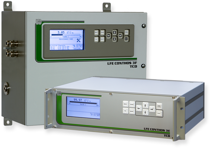
CONTHOS 3E-TCD

General purpose
19" rack housing
(protective class IP40)
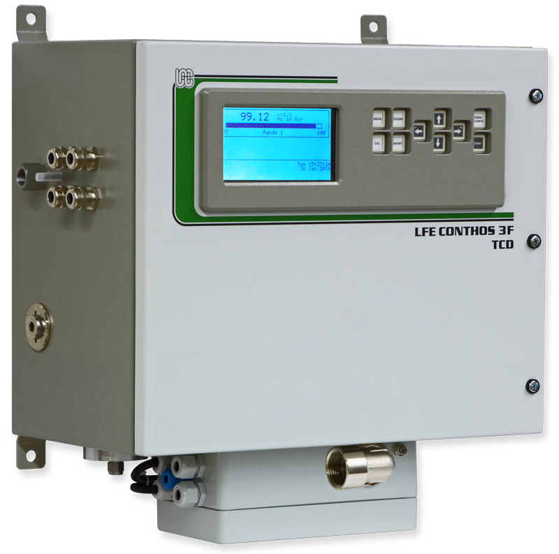
CONTHOS 3F-TCD

General purpose
Field housing
(protective class IP65)
CONTHOS 3F-TCD Ex p
Explosion protected
ATEX version for ex zones 1 & 2
CONTHOS 3F-TCD HT
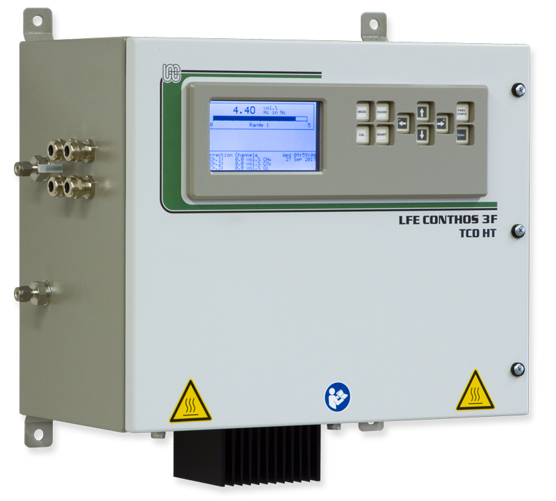
High temperature version
General purpose
Field housing
(protective class IP65)
Options
- Up to 3 switchable ranges: independently configurable, suppressed & absolute (non-suppressed)
- Dynamic interference correction of accompanying components in multi-component gas mixtures in conjunction with external, selective gas analyzers
- Digital I/O board for remote range switching, range identification, threshold contacts, etc.
- RS-485 interface with Modbus RTU protocol
- Modbus TCP
Technical data
Technical Data
Enclosure & Electrical Data
| CONTHOS 3E 19”-rack housing | CONTHOS 3F field housing | CONTHOS 3F - Ex p ATEX compliant Ex p system | CONTHOS 3F - HT high temperature version | |
|---|---|---|---|---|
|
Technical specifications subject to change without notice |
||||
|
|
|
|
|
|
for mounting in 19" cabinet |
purgeable steel housing for wall mounting; with separate compartments for the electronic components and the analytical components |
|||
|
Enclosure & electrical data |
||||
|
Dimensions |
133 x 483 x 427 mm |
490 x 460 x 270 mm |
502 x 460 x 270 mm |
|
|
Protection class |
IP40 |
IP65 |
||
|
Electrical hazardous area class |
Protection type "px" for zones 1 & 2 according to EN 60079 Ex protective class of system: II 2 G, Ex p II T4 |
|||
|
Weight |
approx. 10 kg |
approx. 25 kg |
approx. 30 kg |
approx. 25 kg |
|
Power requirements |
100-240 VAC (48-62Hz; nominal voltage range: 88-253 VAC; 100 VA max. during warm-up period) |
|||
Measuring Characteristics
|
Common Technical Data | ||||
|---|---|---|---|---|
|
Technical specifications subject to change without notice |
||||
|
Measuring characteristics |
||||
|
Measuring principle |
Thermal conductivity (TCD). Difference in thermal conductivity (Δλ) of various gases |
|||
|
Measuring ranges |
Up to 3 linearized, independently configurable, switchable ranges. lowest range: 0 - 0.5% H2 in N2 or 99.5-100% H2 in N2 (or equivalent Δλ) |
|||
|
Calibration |
Manual: 2-point (zero / span) calibration |
|||
|
Warm-up time |
dependent upon TCD operating temperature as well as the ambient temperature: |
|||
|
Response time t90 |
≤ 3 sec (at 60 l/h gas flow and minimum signal dampening level) |
|||
|
Influence of gas flow |
between 3 - 30 l/h: < 0.5% of range span for a gas flow change of ±10 l/h Higher flow rates up to e.g. 120 l/h are possible. At these higher flow rates it is recommended that the analyzer be calibrated at the operating flow rate. |
|||
|
Pressure influence |
The TCD principle has a normally negligible pressure dependency. At very low ranges it can be seen as a proportional signal offset. |
|||
|
Detection limit 1 |
≤ 0.5% of span (at signal dampening level: 1 sec) |
|||
|
Linearity/ Accuracy 1 |
≤ 0.5% of span |
|||
|
Reproducibility 1 |
≤ 0.5% of span |
|||
|
Response drift 1 |
Zero: ≤ 1% of span per week |
|||
|
Ambient temperature influence |
Zero: ≤ 1% of span per 10 K |
|||
|
Ambient temperature in operation |
allowed temperature range : +5 to +45°C |
|||
|
Influence of inclination |
no influence |
|||
Materials
| CONTHOS 3E 19”-rack housing | CONTHOS 3F field housing |
CONTHOS 3F - Ex p |
CONTHOS 3F - HT | |
|---|---|---|---|---|
|
Technical specifications subject to change without notice |
||||
|
|
|
|
|
|
Materials in contact with sample gas |
||||
|
TC Detector |
Al2O3-ceramic and sapphire, glass and SiOx-coated Pt measuring filaments |
|||
|
Internal gas lines |
Standard: PTFE / PFA |
Standard: PTFE / PFA |
Stainless steel tubing |
|
|
Sample gas connectors |
Standard: stainless steel (SS 316; similar to 1.4401) |
|||
|
Optional: Swagelok® connectors for ø¼" tubing |
Optional: Swagelok® connectors for ø¼" tubing |
Optional: Swagelok® connectors for ø¼" tubing |
||
|
Optional : PFA connectors for synthetic tubing DN 4/6 |
||||
Instrument Interface
|
Common Technical Data | ||||
|---|---|---|---|---|
|
Technical specifications subject to change without notice |
||||
|
Data display, inputs and outputs |
||||
|
User Interface |
LC-display (40 characters x 16 lines) + bar graph |
|||
|
Analog signal output |
2 independently configurable, galvanically isolated analog outputs (with common ground; RLoad = 600 Ohm max) |
|||
|
Digital outputs |
Instrument status (NAMUR NE 107 compliant) via floating contacts (28 V max.; 350 mA max.) |
|||
|
Analog inputs |
3 galvanically isolated, configurable analog inputs for interference correction |
|||
|
Interference correction |
3 correction channels for static and/or dynamic interference correction (dynamic correction only in conjunction with the optional analog inputs or Modbus interface (RS-485 or TCP) |
|||
|
Digital I/O |
Digital inputs: 8 configurable, optically isolated inputs (6 - 24 VDC; 10 mA max.)
Digital outputs: 7 configurable, floating relay contacts (28 V max.; 350 mA max.)
|
|||
|
Modbus interface |
|
|||
|
Service interface |
non-isolated serial interface for accessing the instrument's configuration via a proprietary PC software |
|||
1 at constant temperature and pressure
- The stability data is valid for analyzer operation with pure bottled gases. Instrument accuracy is based on binary or quasi-binary gas mixtures. Deviations from the above data can occur in conjunction with process gases depending upon the gas quality and the degree of gas handling.
- Unless otherwise specified the CONTHOS gas analyzer is neither ex-proof nor intrinsically safe in terms of explosion protection.
- The CONTHOS may not be employed for the analysis of ignitable gas-mixtures. The customer must ensure compliance with applicable regulations when using the analyzer with inflammable or toxic gases or when installing within explosion endangered environments.
- The customer must ensure that the sample gas is dry and free of particulates.
Downloads
Downloads 
CONTHOS 3-TCD | Thermal Conductivity Gas Analyzer
Application Questionnaire
CONTHOS 3 TCD Application questionnaire
Brochures
CONTHOS 3-TCD | Thermal Conductivity Hydrogen Gas Analyzer - Product highlights
Product Data Sheets
CONTHOS 3-TCD | Thermal Conductivity Hydrogen Gas Analyzer
CONTHOS 3-TCD Ex p | ATEX Thermal Conductivity Hydrogen Gas Analyzer
CONTHOS 3-TCD HT | High Temperature Thermal Conductivity Hydrogen Gas Analyzer
CONTHOS 3
Sample Applications
Iron and Steel production – blast furnace - Process Gas Analyzer
Heat Treatment and Hardening Process - Hydrogen Process Gas Analyzer
Water Electrolysis Process - Hydrogen Process Gas Analyzer
Hydrogen Cooled Generators - TCD Process Gas Analyzer
Coal Gasification Gas Processing - Process Gas Analyzer
Air Separation Plant and Bottling - Process Gas Analyzer
Synthesis Gas - Syngas Processing - Hydrogen Process Gas Analyzer
High Temperature Applications - Hydrogen Process Gas Analyzer
Refinery Continuous Catalyst Regeneration - TCD Process Gas Analyzer
Technical specifications subject to change without notice

